


Smarter Scaling with Food and Beverage Process Engineering
The food and beverage industry operates under some of the toughest regulations to protect public health and safety.
6 min read
Are you having trouble communicating with different team members about an operational process? Not understanding where something goes in your process, and your co-worker didn’t document it? Or provide a basic sketch? Or a comprehensive blueprint?
If you’re here, you probably already know that understanding how to create a process flow diagram (PFD) is important for many engineering projects. A detailed PFD allows engineers to visualize the entire process, identify inefficiencies, and streamline operations.
So, what is a process flow diagram?
This probably isn’t the first time you’ve wondered about the best way to design a PFD. Or perhaps this is the first time you’ve realized the significant impact a well-crafted PFD can have on your project's success. It's not like process diagrams come with a manual labeled "essential."
Know this: There are several key elements to consider. While they’re not always obvious, there are plenty of clear guidelines that’ll help you create an effective process flow diagram.
A PFD is a technical illustration that represents the flow of materials, energy, and equipment within a process. It’s commonly used in the chemical, mechanical, and industrial engineering fields to map out the core components and their interactions in a process system. Understanding how to create a process flow diagram can help connect the dots between piping connections, and the flow path of materials and energy, and help engineers and technicians understand, analyze, and improve processes.
A PFD's primary purpose is to provide a clear, comprehensive, and simplified visual representation of a process, allowing for a better understanding of the system's functionality to provide consistent efficiency. PFDs are particularly valuable during the design, analysis, and troubleshooting phases, as they highlight the important stages and streamline complex processes into step-by-step segments.
PFD diagrams serve as tools for visualizing and managing the complexities of engineering systems. They allow for:
A process flow diagram provides a visual representation of a process, making it easier for team members, stakeholders, and clients to understand complicated workflows. This visual aid helps bridge communication gaps to keep everyone on the same page. Whether you’re presenting to executives, collaborating with colleagues, or training new employees, a PFD can help visualize details more effectively than text alone.
One of the primary purposes of a PFD is to identify bottlenecks and any inefficiencies in a process. By mapping out each step, you can pinpoint where delays or issues might occur. Illustrating the areas in the engineering process diagram, instead of text, helps engineers better understand where any operational hold-up is.
Creating a process flow diagram helps standardize procedures, keeping everyone following the same, orderly steps. This standardization is key for maintaining quality and consistency, especially in large organizations or production environments. A PFD serves as a reference document that can be used to train new employees, audit processes, and maintain compliance with industry standards.
When issues surface in an engineering process, having a detailed PFD can be a North Star for troubleshooting. The diagram allows you to trace the flow of materials or information and identify where problems might be occurring. This systematic approach to problem-solving can lead to quicker resolutions and more effective solutions without delaying any operational process.
A PFD is not an unchanging document; it should evolve with your processes. Regularly updating and reviewing your PFD helps you implement continuous improvement initiatives.
Understanding the flow of your process is essential for effective resource allocation and planning. A PFD can highlight the resources required at each step, such as personnel, equipment, and materials. This information is invaluable for budgeting, scheduling, and being knowledgeable about how resources are being used efficiently.
In industries with strict regulatory requirements, a PFD can help keep clear compliance. By documenting each step, and its associated controls, you can visualize how to keep within regulations and standards. Additionally, a PFD can assist in risk management by identifying potential failure points and allowing instructions for preventative measures.
As industries move towards automation and undergo digital transformation, having a clear understanding of your processes is key. A PFD provides the foundation for automating workflows and integrating digital tools. By mapping out your process, you can identify areas where automation can be applied in hardware or software that reduces manual tasks and increases performance.
When learning how to create a process flow diagram for your team to plan and execute projects, follow this guide to help keep documentation for compliance purposes.
Creating a PFD involves a structured approach to visualize clarity, accuracy, and usefulness. These steps help streamline the development of a PFD, guaranteeing that it represents the process and meets the needs of all stakeholders involved. Each step is key and builds on the previous one to form a comprehensive diagram. This process can be broken down into four main steps:
To create an effective PFD, it’s important to first define the scope of the process. This involves identifying the start and end points of the process to establish clear boundaries. Determining the level of detail required is also essential; too much detail can complicate the diagram, while too little can exclude any important information. Understanding the purpose of the PFD will help in making these decisions, to make sure that the diagram is fit for use in design, analysis, or troubleshooting.
Before drafting the PFD, gather complete data about each step in the process. This includes:
Accurate and detailed information lays a solid foundation for an effective diagram and minimizes any need for revisions later. To confirm the collected data, collaborate with process operators, engineers, and other key stakeholders to receive firsthand feedback.
Select appropriate symbols that conform to industry standards and make

After drafting the PFD, review it with relevant stakeholders. These might include engineers, process operators, maintenance personnel, and management. Collect their feedback to identify any discrepancies for areas for improvement. Making any necessary edits can help refine the PFD for future ongoing improvements.
Resource: Whether you’re starting from scratch, or redefining your process,
let us help you further to achieve smooth operations.
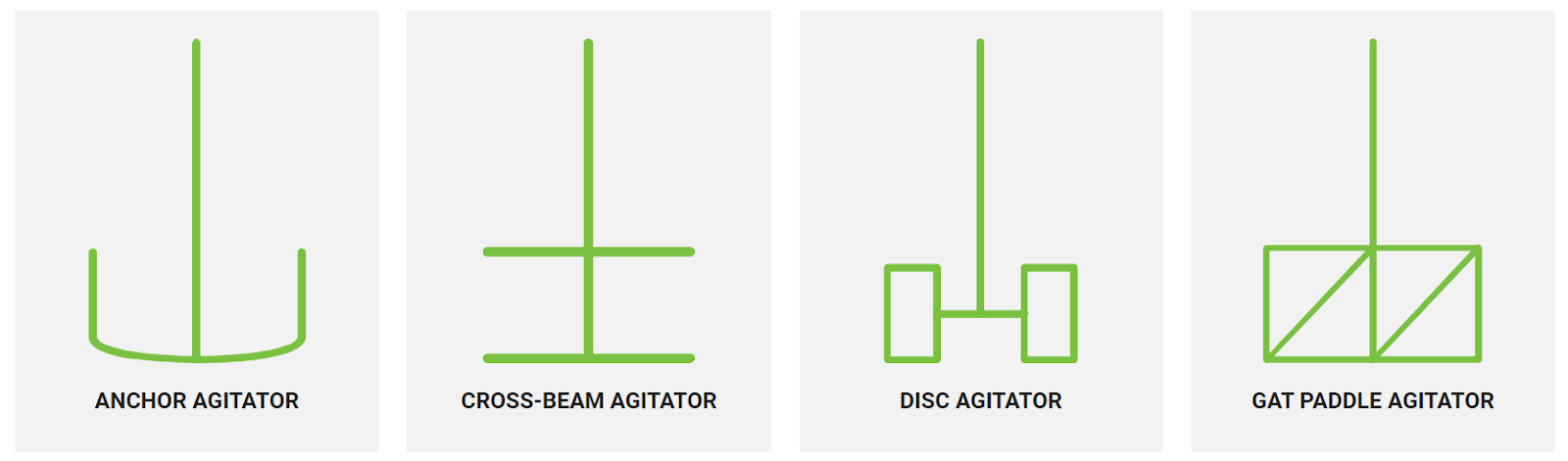
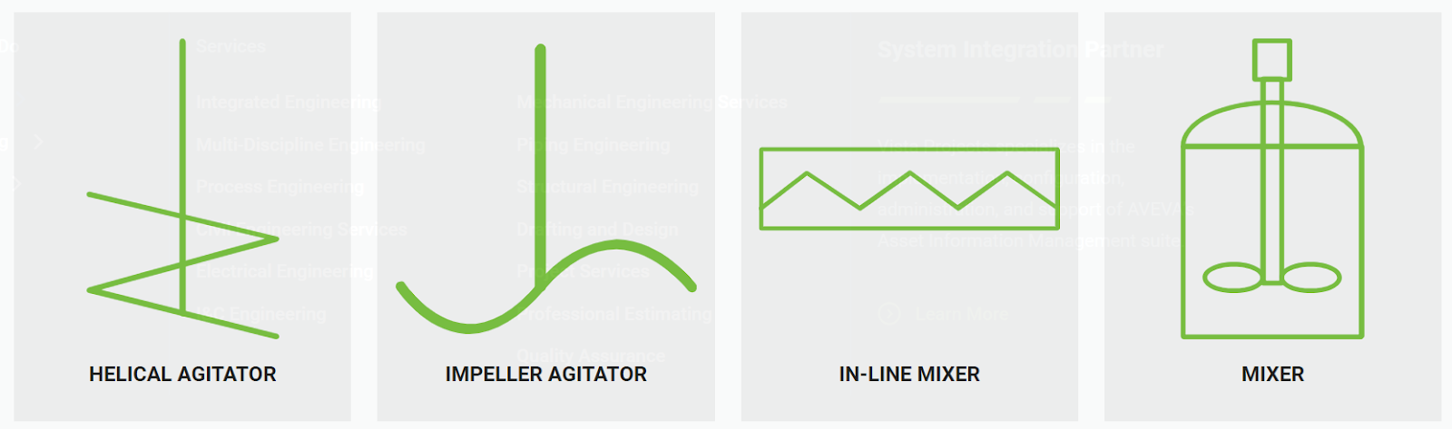
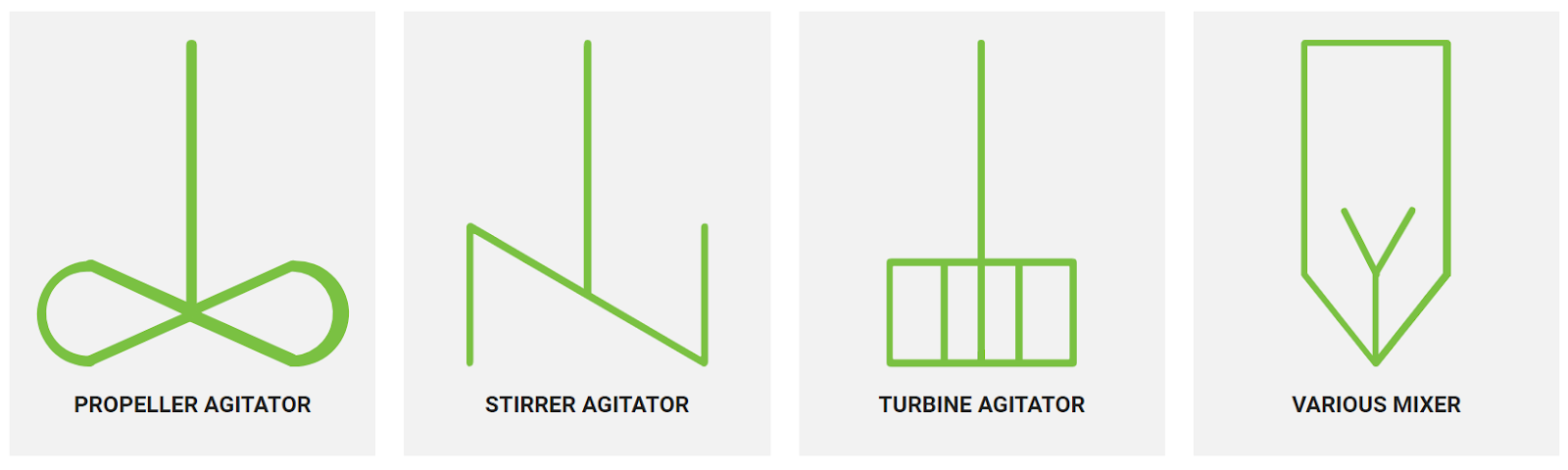
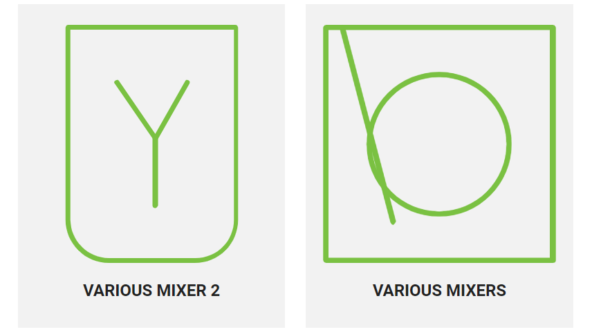
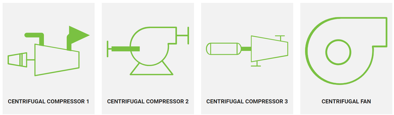
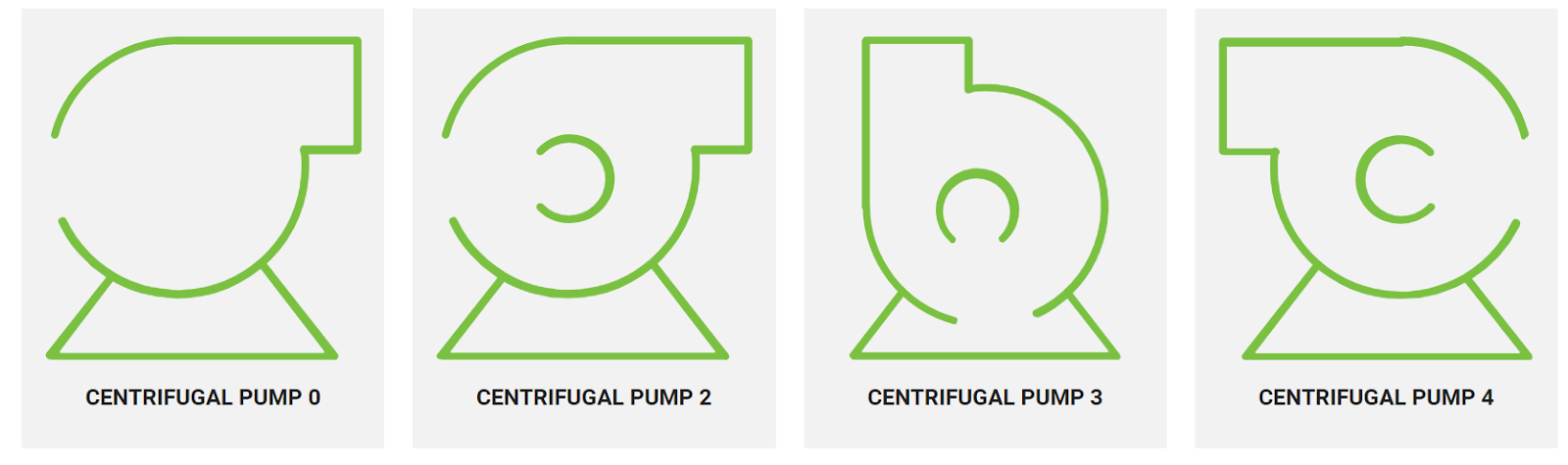
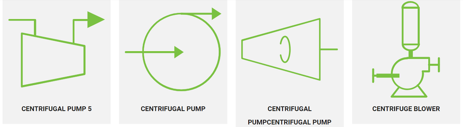
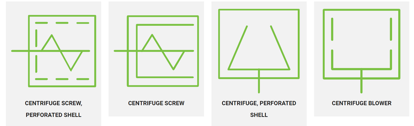
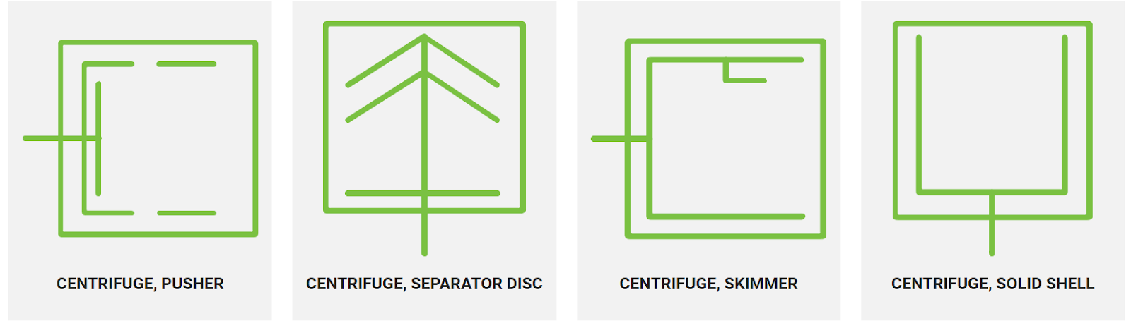
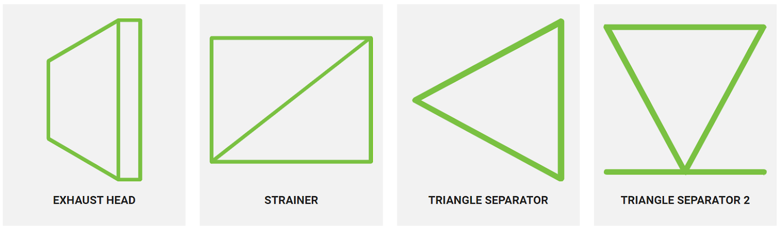
Once the PFD has been crafted and reviewed, it’s time to add symbols. These standard symbols represent various components and actions within a process to provide clear communication of what to expect in a certain field for each engineer involved. Below are some common symbols that are involved for mixers, pumps, and pipes:
Disclaimer: Please consult your lead engineer to make sure what these symbols specifically represent for your company as these are common symbol examples.
Some things to consider to help visualize data and process flow diagrams include:
Organizations need to meet OSHA, EPA, and ISO regulations to make sure their product can pass any necessary inspections before entering the market. PFDs provide a comprehensive record of process flows, which simplifies the documentation process for audits and quality assurance. During audits, PFDs serve as a key reference to simplify the validation process for auditors. PFDs provide quick identification of system components, process steps, and control mechanisms, making it easier to demonstrate compliance with quality regulations.
PFDs also facilitate traceability, which is essential for root-cause analysis when investigating quality issues or deviations. This level of detailed documentation is important to keep in mind during inspections and when proving compliance with regulatory standards, to minimize the risk of non-compliance penalties.
To kickstart your creation of a PFD, there are some potential software options to use. The software includes collaborative features that allow any stakeholder involved to create and validate the best engineering flow diagram. The common software that engineers use to streamline their processes:
Utilizing PFDs as a training tool significantly boosts the onboarding process for new employees. By providing a visual representation of process operations, PFDs make it easier for new staff to understand complex workflows and equipment interactions at a quick rate. They serve as educational guides that simplify learning, helping employees grasp operational details without extensive text explanations.
PFDs also improve internal communication by providing a common visual language for discussing processes. This informs all team members, regardless of their department or expertise, to have an understanding of the process flows, which is key for effective collaboration and problem-solving. Regular updates to PFDs also facilitate ongoing training and keep the team informed about any process changes or optimizations.
Creating a process flow diagram ( is more than just plotting out equipment and materials; it’s about visualizing the entire process to provide thorough clarity and accuracy. A simple sketch might be passable for simple and short operation processes, but for an ongoing, complex operational project, a detailed PFD is key.
PFDs open innovative pathways to improve quality and optimize processes. To get the thoroughness your project demands, carefully consider the requirements of your system.
For additional guidance and to explore how we can support your project, contact MXD Process today with your process flow diagramming questions.


The food and beverage industry operates under some of the toughest regulations to protect public health and safety.

A process engineer designs, implements, controls, and optimizes industrial processes, especially continuous ones within the chemical, petrochemical,...
Have you ever wondered how to make every part of your manufacturing process work flawlessly? With Integrated Process Systems (IPS), we're talking...